Frankie gets a lid

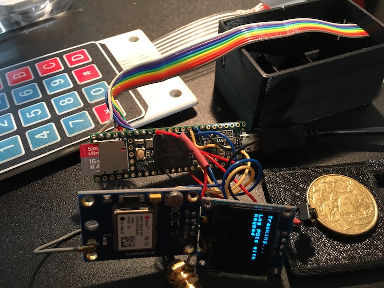
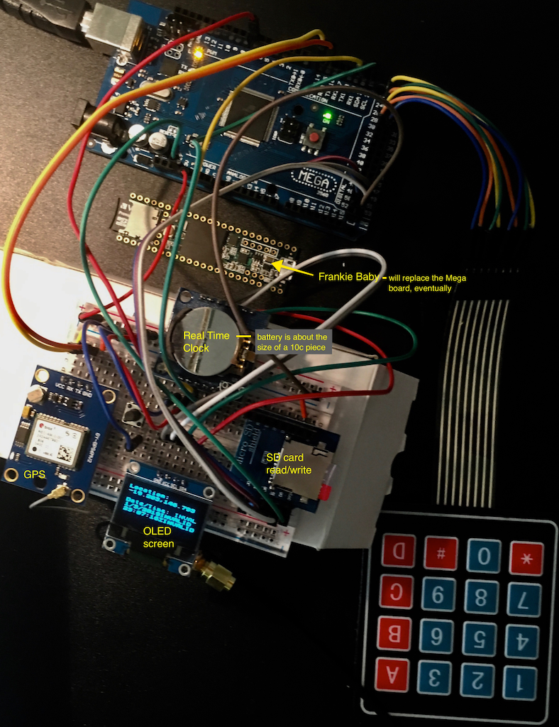
Finally, Frankie now has a 3D-printed lid. Sounds mundane, but this was in many ways the tricky part. It’s in two parts – one holding the keypad, sans suitable labels, the other covering the keypad electronics and holding the OLED screen.

Top view. Keypad will have labels over the numbers…
Underneath the hood

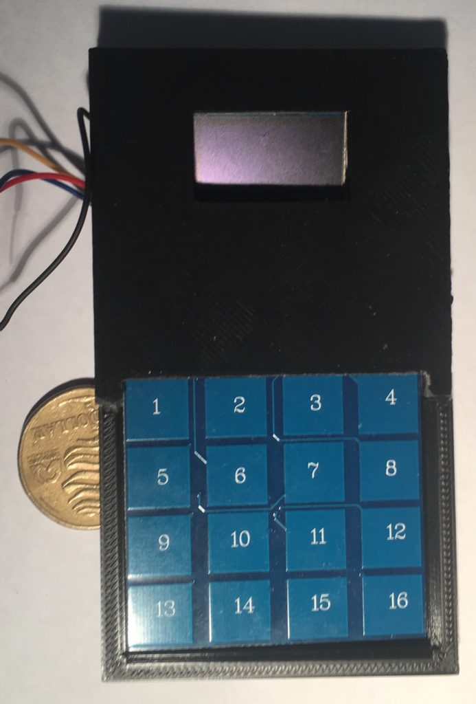
Next, Ill be making the box which the lid fits on to.

Frankie rides again!

Well, Frankie is now a complete working prototype, albeit without a box. The issue with the new type of keypad has been resolved. And, Frankie now runs on LiPo battery power, meaning it can be recharged via USB.

The container will be a different shape – it incorporates the keypad and screen in a single unit, about the size of a mobile phone, only a bit thicker. I don’t have Apple’s, or, indeed, Samsung’s resources immediately available. Boohoo.

Now for the tricky part – 3D printing the container. Well, designing it first.

Keypad problem solved

Teensy with new keypad

Ok, I’ve chosen a new type of keypad that is probably more suitable as it is rigid and can be incorporated in the device itself. I had tried this keypad before but could not get it to work properly, but now, using interrupts that allow me to detect rising and falling voltages, it works well. This image also shows how everything is connected up to the Teensy. I’ve build the rechargeable battery module so we’re ready to go from an electronics standpoint. Now, I just have to redesign the box it all goes into…

Power supply

Issues with the keypad

All the components are ready to go into the snazzy new box, but there seems to be a major issue with the keypad. The keypad is a 4×4 matrix, ie 4 rows and 4 columns. The electronics work by detecting which row and which column are pulled HIGH, hence identifying which key has been pressed (think of a ‘spreadsheet-type configuration, so R1C1 is the number ‘1’, R3C2 would be ‘8’). However, at the moment, R2 identifies as as R1, ie R! and R2 give the same row signal. I don’t know why… Probably the best solution is to convert the keypad to an I2C configuration.

All ready to get jammed into the snazzy new black box, BUT…

Tracking data and data logging issues

As the project moved more towards data collection for co-performed place-making, it became more evident that the tagging of multiple types of waypoints during a walk, while a feasible activity for the research team, was a big ask for any project participants. We need a much simpler way of tagging the GPS routes with distinct waypoints.

This is a design concept that underpins the current low fidelity app design.

It also inspires the direction that the hardware design took.

A conversation with a colleague who used to work with data collection for Parks and Wildlife provided some insights. They also have occasional need to note specific data types attached to waypoints (specific feral cats or specific weeds for example) and used a keyboard input data logger.

Probably something like this one – note the cable input

Commercial multi-event data loggers that allow customizable key inputs are not common. Our next step was to develop our own:

A work in progress …

Early design concepts: capturing the dog’s experience

A major aspect of the earliest design concepts for the project is the idea that the companion animal is an important co-performer in the experience and the place-making that occurs during the walk.

Early design work proposed a bluetooth dongle for the dog that would be activated on attachment of a lead and which would generate a UID. The idea was that any community networks would be generated through the dogs themselves.

Once the walker actively joins the local network, their dog would be displayed as a presence on the map, providing the basis for ‘trusted networks’ in much the same way that we do tend to make stronger connection with other walkers whose dogs get on with our own.  Trusted networks can then be created through Physical Community Exchanges (PCEs), generated when two Bluetooth devices (two dogs) come into proximity. Walkers would be alerted by the mobile device and then have the option of adding each other to a personal network. 

Pathways and Paws(es) 2018
Walker’s view of network showing other (network member) dogs
Early hardware explorations for Bluetooth dongle construction

This early low-fi prototype is still a work in progress. This particular sub-project has been mothballed somewhat in favor of a focus on the data collection.

Dog tracking

While a COTS GPS tracking app is appropriate for the human partner in the co-performance, what about the companion animal?

Taking the lead from Craig Taylor, we used a GPS Route Logger Dongle that was small enough to attach to the dog’s collar and that would simply generate GPX files.

This was attached to the dog with a second soft collar and a small bag so that it didn’t dangle in the dog’s way.


Canmore GT-730FL-S GPS data logger [Review]

The Canmore seems to work well. The dongle has a quick waypoint generator in the form of a button – somewhat impractical while the dog is wearing it – although she did manage to activate it once or twice through active movement.

Does require proprietary software to download GPX files (supplied) which only works on a PC.

GPS trace generated by dog

Pathways & Paws(es)

First version of the EthnoBox – 3D print

Even for a simple structure like this one, there are a lot of dimensions. So, inevitably, not everything is perfect. Welcome to the world of 3D printing, where nothing is ever perfect!

Roughly 65mm x 35mm x 34mm. The cutout is for a small OLED screen. The device will be powered by 3 AAA batteries in the first instance. NB, the Teensy has an SD card reader/writer onboard.

DevBlog happens here – use categories to tag items for menus